










Selecting the right building wire for large-scale construction projects is one of the most critical decisions that electrical engineers, project managers, and contractors face. Unlike residential or small commercial installations, large construction projects—think high-rise towers, industrial complexes, hospitals, data centers, and manufacturing facilities—demand a level of precision, foresight, and technical expertise that goes far beyond simply matching wire size to breaker rating. The consequences of poor wire selection can be devastating: equipment failures, safety hazards, project delays, regulatory penalties, and millions of dollars in unnecessary costs.
This comprehensive guide walks you through every factor that must be considered when choosing building wire for large construction projects. From understanding the governing codes and standards to evaluating conductor materials, insulation types, ampacity requirements, voltage drop calculations, and installation environments, we will cover the complete decision-making framework that separates successful projects from costly failures.
Understanding the Regulatory Framework
Before any discussion of wire types, sizes, or installation methods, one fundamental truth must be established: every building wire selection in the United States must comply with the National Electrical Code (NEC), published by the National Fire Protection Association (NFPA) as NFPA 70. The NEC is not merely a suggestion—it is law in most jurisdictions, and violations can result in failed inspections, stop-work orders, and legal liability.
For large construction projects, the NEC provides the baseline requirements, but it is rarely the only standard that applies. Many projects must also satisfy additional requirements from local building codes, industry-specific standards (such as those from the Institute of Electrical and Electronics Engineers, or IEEE), and client specifications. Understanding which standards govern your project is the essential first step, as these documents will dictate everything from minimum wire sizes to allowable insulation types to installation clearances.
Article 310 of the NEC is the primary reference for conductor sizing and insulation specifications. It provides the ampacity tables that determine how much current a given wire can carry under various conditions, as well as the temperature ratings that dictate how hot a wire can safely operate. For large projects, however, the NEC’s requirements are often just the starting point—many engineering firms develop their own internal standards that exceed code minimums to ensure reliability and longevity.
It is also worth noting that large construction projects frequently involve multiple regulatory jurisdictions. A project spanning state lines or operating under federal oversight may need to satisfy requirements from the Occupational Safety and Health Administration (OSHA), the Environmental Protection Agency (EPA), or even the Department of Defense. Engaging a qualified electrical engineer who understands the full regulatory landscape is not optional—it is essential.
Conductor Materials: Copper vs. Aluminum
One of the most fundamental decisions in building wire selection is the choice of conductor material. The two primary options are copper and aluminum, and each has distinct advantages and disadvantages that make it suitable for different applications within large construction projects.
Copper has long been the gold standard for building wire. Its superior electrical conductivity means that a copper conductor can carry more current than an aluminum conductor of the same size. Copper also offers excellent corrosion resistance, superior ductility, and a proven track record of reliability over decades of service. For critical circuits—such as those serving life safety systems, emergency generators, and sensitive electronic equipment—copper remains the preferred choice. The higher cost of copper is often justified by its performance advantages and the reduced risk of connection failures over time.
Aluminum, on the other hand, offers significant cost savings and weight advantages. Pound for pound, aluminum has about twice the conductivity of copper, meaning that an aluminum conductor can be lighter than its copper equivalent for the same current-carrying capacity. This weight reduction can translate into substantial savings in large projects, particularly for long feeder runs where the weight of the cable affects structural support requirements. However, aluminum has historically been associated with connection reliability issues, primarily due to oxidation and thermal expansion differences that can cause terminations to loosen over time. Modern aluminum alloys and specially designed connectors have largely addressed these concerns, but proper installation practices remain critical.
The choice between copper and aluminum is rarely a simple one. Many large projects use both materials strategically: copper for critical and sensitive circuits, and aluminum for large feeders where cost and weight savings are most impactful. Understanding the specific requirements of each application within your project is the key to making the right decision.
Insulation Types and Their Applications
The insulation system of a building wire determines its temperature rating, moisture resistance, chemical compatibility, and overall durability. For large construction projects, where wires may be exposed to extreme temperatures, moisture, chemicals, or physical abuse, selecting the right insulation type is just as important as selecting the right conductor size.
THHN/THWN-2 is perhaps the most common building wire type used in commercial and industrial construction. This insulation system offers a 90°C rating in dry locations and a 75°C rating in wet locations, making it versatile enough for most interior applications. THHN stands for Thermoplastic High Heat-resistant Nylon-coated, while THWN adds a Water-resistant rating. The nylon coating provides excellent abrasion resistance, making this wire suitable for pulling through conduit and raceways. For the vast majority of general-purpose circuits in large buildings, THHN/THWN-2 is the go-to choice.
XHHW-2 (Cross-linked High Heat-resistant Water-resistant) represents a step up in performance. The cross-linked polyethylene insulation offers superior resistance to moisture, chemicals, and heat, with a 90°C rating in both dry and wet locations. XHHW-2 is often specified for industrial environments where exposure to oils, solvents, or extreme temperatures is a concern. While more expensive than THHN, the added durability can be worth the premium in demanding applications.
USE-2 (Underground Service Entrance) is designed specifically for direct burial applications. Its rugged insulation and moisture resistance make it suitable for underground feeders, though it requires additional mechanical protection when exposed to physical damage. For large projects with extensive underground distribution systems, USE-2 is a common specification.
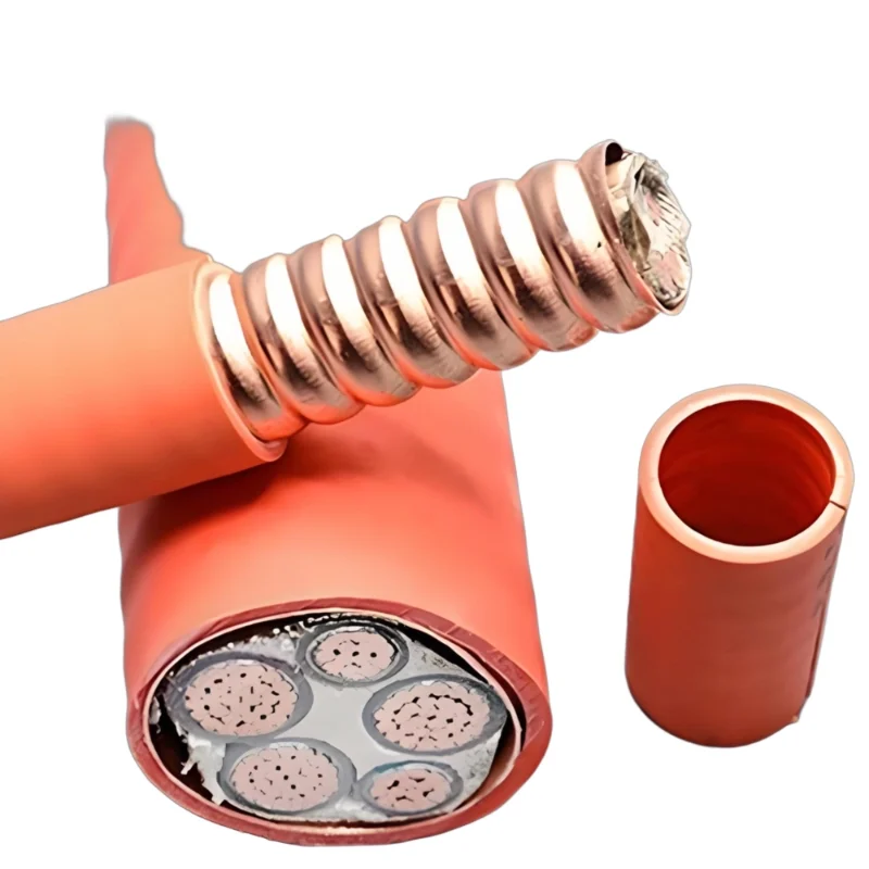
MC Cable (Metal-Clad Cable) and AC Cable (Armored Cable) incorporate a metallic armor that provides both mechanical protection and, in some cases, a grounding path. These cable types are frequently used in large construction projects for feeder circuits in areas where physical protection is required without the need for separate conduit. The armor also serves as an equipment grounding conductor in many configurations.
Tray Cable is another important category for large projects, particularly those with extensive cable tray systems. These cables are designed to be installed in cable trays and often feature enhanced flame-retardant and smoke-limiting properties. Industrial facilities and large commercial buildings frequently use tray cable for power and control circuits.
Understanding the full range of insulation options and their respective performance characteristics allows you to match the right building wire to each specific application within your project.
Ampacity and the Art of Sizing
Ampacity—the maximum current a conductor can carry continuously without exceeding its temperature rating—is perhaps the most frequently misunderstood aspect of building wire selection. Many assume that wire sizing is simply a matter of looking up a number in a table, but the reality is far more complex.
The NEC provides ampacity tables that specify allowable currents for various conductor sizes, insulation types, and temperature ratings. However, these table values are based on specific assumptions about installation conditions that rarely match real-world projects exactly. When conditions differ from the assumptions—as they almost always do—correction factors must be applied.
Ambient temperature is one of the most significant factors affecting ampacity. The NEC ampacity tables assume an ambient temperature of 30°C (86°F). When the installation environment is hotter, the conductor’s ability to dissipate heat is reduced, and the ampacity must be derated accordingly. Conversely, cooler environments may allow higher ampacities, though this is rarely relied upon in design. For large construction projects, where electrical rooms, mechanical spaces, and rooftop installations often experience elevated temperatures, ambient temperature correction is a critical consideration.
Conductor bundling is another major factor. When multiple current-carrying conductors are bundled together in a conduit, cable tray, or raceway, their ability to dissipate heat is reduced. The NEC requires derating when more than three current-carrying conductors are present in a raceway or cable. In large projects, where conduits and trays are often packed with conductors, this derating can significantly reduce the effective ampacity and require larger wire sizes than would otherwise be necessary.
Continuous loads—those expected to operate for three hours or more—require special consideration. The NEC mandates that conductors for continuous loads be sized at 125% of the continuous load current. This means that a circuit serving a continuous 100-amp load must be sized for at least 125 amps before any other derating factors are applied. In large commercial and industrial facilities, where many loads operate continuously, this requirement has a substantial impact on wire sizing.
The interplay of these factors means that wire sizing in large projects is rarely straightforward. A thorough ampacity calculation must consider the specific installation conditions, apply all relevant correction factors, and verify that the selected wire meets both the ampacity requirements and the voltage drop limitations. This is work best performed by experienced electrical engineers using recognized calculation methods.
Voltage Drop: The Hidden Performance Killer
While ampacity ensures that a wire does not overheat, voltage drop ensures that equipment receives adequate voltage to operate properly. Voltage drop is the reduction in voltage that occurs as current flows through a conductor due to its resistance. In large construction projects, where feeder runs can extend hundreds or even thousands of feet, voltage drop can become a significant performance issue.
Excessive voltage drop causes motors to draw more current, lights to dim, electronic equipment to malfunction, and overall system efficiency to decline. The NEC does not mandate specific voltage drop limits except for a few specialized applications, but industry best practice recommends limiting voltage drop to 3% for branch circuits and 2% for feeders, with a total of 5% from the service point to the farthest outlet.
Calculating voltage drop requires knowledge of the conductor material, size, length, and the current being carried. For long runs, the voltage drop may dictate a larger wire size than would be required by ampacity alone. This is particularly common in large buildings where distribution equipment is centralized and feeders must travel long distances to reach loads.
Several strategies can mitigate voltage drop in large projects. Increasing conductor size is the most direct approach, though it adds cost and weight. Running multiple parallel conductors can also reduce voltage drop while potentially offering installation advantages. In some cases, adjusting the system voltage—such as using 480V instead of 208V for distribution—can dramatically reduce voltage drop for the same power delivery. Transformers located close to loads can also help maintain proper voltage levels.
Voltage drop considerations must be integrated into the wire selection process from the beginning. Waiting until the design is complete to check voltage drop often results in costly redesigns or performance compromises. A proactive approach that considers voltage drop alongside ampacity, installation constraints, and cost will yield the most efficient and reliable design.
Environmental and Installation Factors
Large construction projects present a diverse range of installation environments, each with its own challenges and requirements for building wire selection. Understanding these environmental factors is essential for ensuring long-term reliability and code compliance.
Temperature extremes are common in many large projects. Rooftop installations can expose wires to intense solar heating, while unheated mechanical spaces in cold climates may see freezing temperatures. Wires must be rated for the temperatures they will encounter, both during operation and during installation. Cold-weather installation may require special handling to prevent insulation cracking, while high-temperature locations may require wires with higher temperature ratings or derating of ampacity.
Moisture and water exposure is another critical consideration. Underground installations, outdoor runs, and locations subject to condensation or flooding all require wires with appropriate moisture resistance. THWN, XHHW, and USE are all rated for wet locations, but the specific requirements depend on the nature and duration of water exposure. Direct burial applications require additional protection against mechanical damage and corrosion.
Chemical exposure is common in industrial facilities, laboratories, and some commercial buildings. Wires installed in areas with exposure to oils, solvents, acids, or other chemicals must have insulation systems that resist chemical attack. XHHW and other cross-linked insulations generally offer superior chemical resistance compared to thermoplastic alternatives.
Physical protection requirements vary widely across a large project. Wires installed in accessible areas, exposed to potential physical damage, or subject to vibration must be protected by conduit, armor, or other means. The choice between conduit and cable systems often depends on the level of protection required and the installation logistics.
Cable tray systems are widely used in large construction projects to organize and support large numbers of cables. Tray cables are specifically designed for this application and must meet requirements for flame propagation, smoke generation, and mechanical robustness. The selection of tray cable involves considerations of tray fill, cable spacing, and the specific tray type being used.
Fire safety is a paramount concern in all construction projects. Wires installed in air-handling spaces (plenums) must be rated for low smoke and flame spread. Plenum-rated cables (CMP) are required in these spaces under most building codes. For other areas, riser-rated cables (CMR) may be sufficient, though local codes may impose additional requirements.
Sizing for Future Expansion
One of the most common mistakes in large construction projects is designing the electrical distribution system for the initial load only, without considering future growth. Buildings are rarely static; they evolve over time as tenants change, equipment is upgraded, and operations expand. Designing for future expansion is not just prudent—it is often required by owners who want to avoid costly upgrades down the road.
Sizing building wire for future expansion means considering not only the current load but also the anticipated load growth over the building’s expected life. This may involve installing larger feeders than the initial load requires, providing spare conduit capacity for future circuits, or designing distribution systems with built-in capacity for additional loads.
The cost of oversized wire at the time of initial installation is almost always less than the cost of replacing wire later. Conduit, labor, and disruption are expensive, and retrofitting a building with new feeders can be extremely challenging. For large projects, the incremental cost of upsizing wire by one or two gauge sizes is often a wise investment.
However, future-proofing must be balanced against first cost. Not every circuit needs to be oversized; a strategic approach identifies the feeders and branch circuits most likely to need expansion and sizes them accordingly. Working closely with the building owner to understand their long-term plans is essential for making these decisions.
Cost Considerations Beyond the Wire Itself
The cost of building wire is only one component of the total installed cost, and focusing solely on wire price can lead to poor decisions. Installation labor, conduit and raceway costs, termination materials, and long-term maintenance all factor into the total cost of ownership.
Installation labor often exceeds the material cost of the wire itself, particularly for large conductors that are difficult to handle and terminate. Wires that are easier to pull, strip, and terminate can reduce labor costs significantly. Factors such as insulation flexibility, weight, and the availability of pre-made terminations all affect installation efficiency.
Conduit and raceway costs are closely tied to wire selection. Larger wires require larger conduits, which increase material and installation costs. In some cases, using a more expensive wire with a smaller overall diameter can allow for smaller conduits, resulting in net savings. Similarly, selecting cables that do not require conduit—such as MC Cable or tray cable—can eliminate conduit costs entirely.
Termination costs vary significantly between wire types. Aluminum wire requires special connectors and installation techniques that add to labor and material costs. Some insulation types are more difficult to strip than others, adding to termination time. These costs may be small on a per-termination basis but can add up significantly across a large project.
Long-term maintenance and reliability costs are often overlooked but can be substantial. Wires that are prone to connection failures or insulation degradation will require more frequent maintenance and may cause unplanned downtime. Investing in higher-quality wire and proper installation practices can reduce these long-term costs.
Working with Suppliers and Manufacturers
The relationship between the project team and wire suppliers can have a significant impact on the success of a large construction project. Suppliers who understand the project’s requirements, can provide technical support, and can deliver materials on time are invaluable partners.
Technical support from wire manufacturers can help with complex selection decisions, particularly for unusual applications or when navigating conflicting code requirements. Many manufacturers employ experienced electrical engineers who can provide guidance on ampacity calculations, voltage drop, and installation practices.
Product availability is a critical practical consideration. Large construction projects require enormous quantities of wire, and delays in material delivery can derail schedules. Working with suppliers who have adequate inventory and reliable supply chains is essential. In some cases, placing orders far in advance may be necessary to secure the required quantities.
Quality assurance is another important consideration. Wire that does not meet specifications—whether due to substandard materials, manufacturing defects, or damage during shipping—can cause failures and delays. Reputable suppliers with robust quality control processes reduce these risks.
Cost negotiation is a reality of large projects, but price should never be the sole deciding factor. The lowest-priced wire may not be the best value if it leads to installation difficulties, reliability issues, or code compliance problems. A balanced approach that considers total cost of ownership will yield better results.
Documentation and Traceability
In large construction projects, documentation is not an afterthought—it is a requirement. Every wire installed must be traceable to its specifications, test reports, and installation records. This documentation serves multiple purposes: it provides evidence of code compliance, supports warranty claims, facilitates future maintenance and upgrades, and protects against liability.
Wire specifications should be documented in the project’s electrical drawings and specifications. These documents should clearly identify the wire type, size, insulation rating, and any special requirements for each application. Ambiguity in specifications leads to errors and disputes.
Test reports from the wire manufacturer provide evidence that the wire meets its stated specifications. These reports should be reviewed and retained as part of the project record. For critical applications, independent testing may also be required.
Installation records document where each wire was installed, including the routing, termination points, and any special conditions encountered. These records are invaluable for troubleshooting and future modifications.
As-built drawings reflect the actual installed configuration, including any changes made during construction. These drawings should accurately document the wire types and sizes used, as well as any deviations from the original design.
Conclusion: A Systematic Approach to Wire Selection
Choosing building wire for large construction projects is a complex endeavor that requires expertise across multiple disciplines. The stakes are high: poor decisions can lead to safety hazards, equipment failures, regulatory violations, and significant cost overruns. Yet with a systematic approach that considers all relevant factors, the task becomes manageable.
The process begins with a thorough understanding of the applicable codes and standards, followed by a careful evaluation of the project’s specific requirements. Conductor material, insulation type, ampacity, voltage drop, environmental conditions, installation methods, and future expansion needs must all be considered in an integrated fashion. Cost considerations must extend beyond the initial wire price to include installation, termination, maintenance, and long-term reliability.
Throughout the process, collaboration is key. Electrical engineers, contractors, suppliers, and building owners must work together to develop a wire selection strategy that meets technical requirements, budget constraints, and schedule demands. Documentation must be maintained to ensure traceability and support future needs.
Large construction projects present unique challenges, but they also offer opportunities to implement best practices that will serve the building and its occupants for decades. The wire selected today will carry power through the building’s entire life, making the selection process one of the most important decisions in the project’s electrical design.
By following the comprehensive framework outlined in this guide, project teams can navigate the complexities of building wire selection with confidence, delivering safe, reliable, and cost-effective electrical systems that stand the test of time. The investment in thoughtful wire selection pays dividends not only during construction but throughout the building’s operational life, making it one of the most valuable investments a project can make.